Build Steps
View Steps 1-2
Step 1

Included in the Front Suspension Components Set is a guide for cutting the opening and drilling the fastener locations accurately for the fuel bladder access panel. The guide is not to be affixed to the tub/monocoque permanently. Select an adhesive that will allow for easy removal of the guide when you are finished using it. I used a low-tact, spray adhesive that didn't leave any residue after I removed it. There are no details on the monocoque to indicate where this opening should be, so refer to photos of the real car, or place the guide according to the image in this guide. As shown in the photo, use the back edge of your hobby blade to scribe the opening location on the inner side of the template. The scribed line will allow you to create a very accurate opening. The holes of the guide are drilled to reflect the openings/locations for the fasteners. Use a #73, a .024", or a 0.6mm twist drill to drill each of the 26 holes on the guide. I used my Foredom (or Dremel) drill chuck using a flexible shaft. Please note, that the drill under power grabs very quickly and pulls itself through the plastic rapidly. I would recommend using a pin vise and drilling the holes by hand.

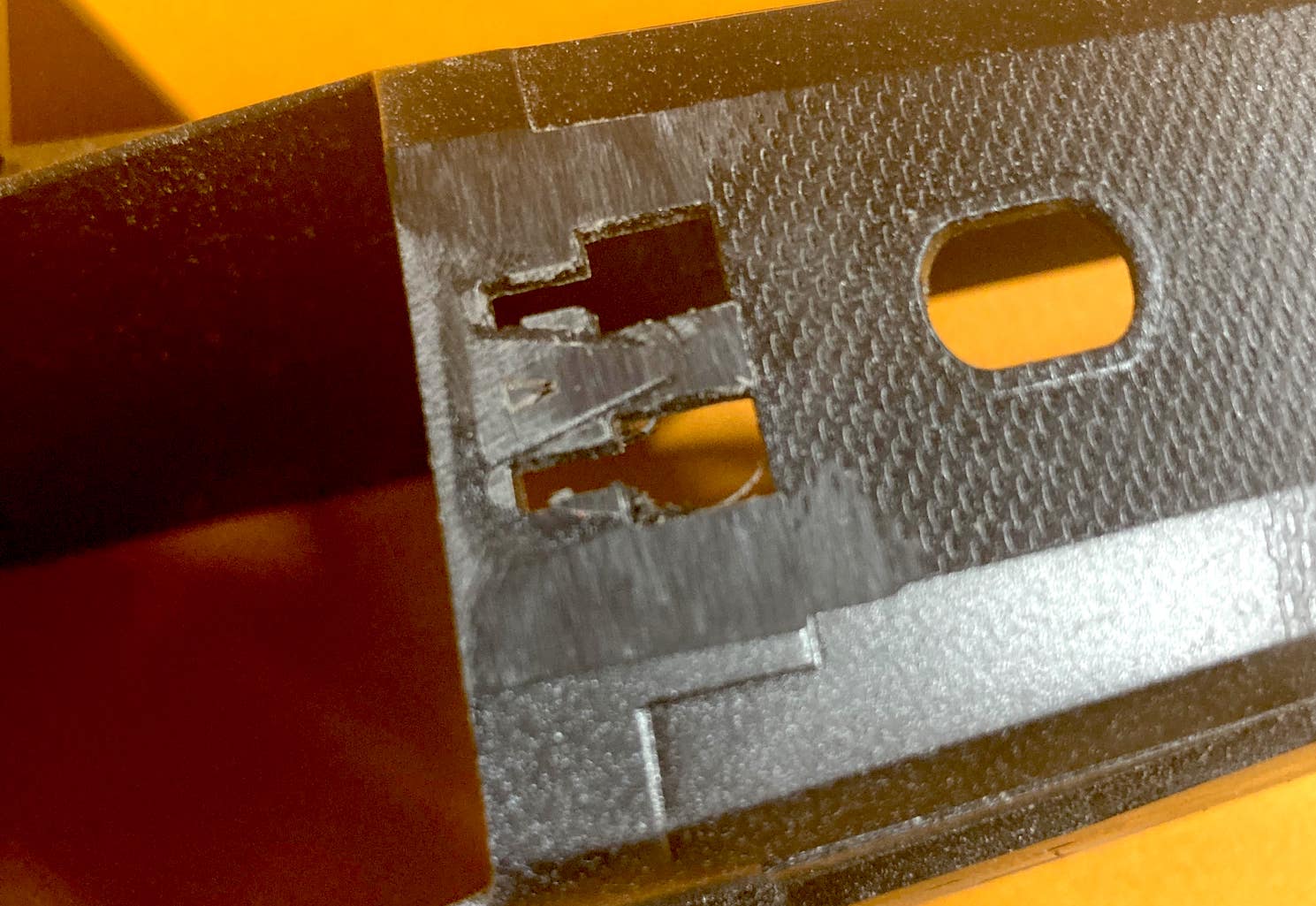
Your tub/monocoque should look like like. Larger holes have been drilled to facilitate quick removal of material where the opening will be. I used a .125” (1/8" or 3 mm) drill to make the crude pattern shown to get material out of the way, and I could finish getting the rough opening accomplished using a pair of sprue cutters. Use whatever drill size you are comfortable with to drill these larger holes. Again, I used my Foredom (or Dremel) to drill the holes, but if you prefer to have the holes closer to the scribed line, I would recommend drilling them by hand.

Here, you can see the rough opening that will now allow us to begin the more precise work of getting this opened up to match the scribed line.

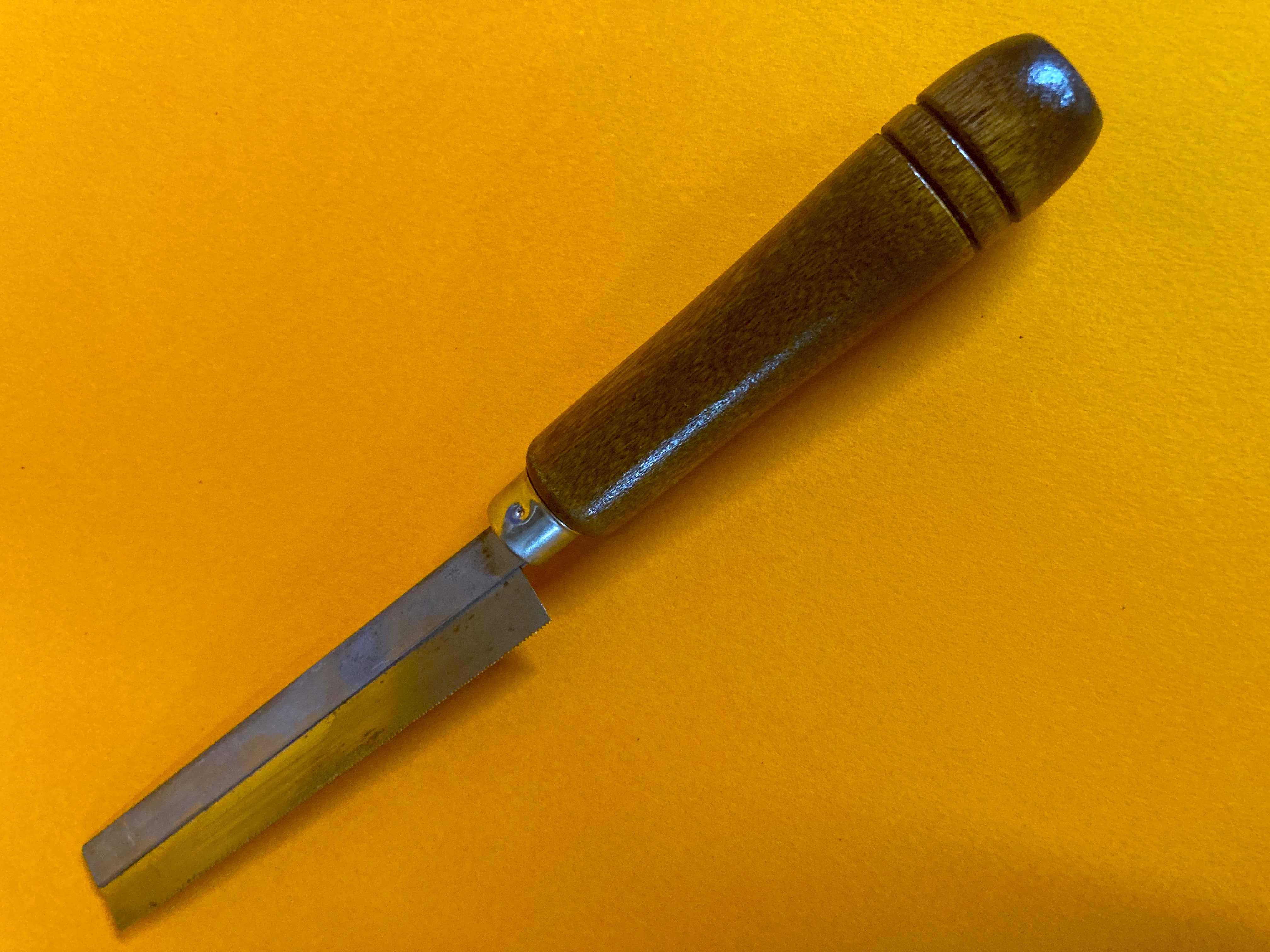
These are the tools I used ready the opening to accept the fuel bladder access panel. The fuel bladder access panel is included in the Front Suspension Set. Use it as your reference while creating the opening. When I was getting close to the scribed line, I relied upon my hobby knife to finalize it's shape. The plastic in this kit is thick, and it seems to be pretty tough, so using a round and flat, metal file (or fingernail filing stick) to finish the opening. Using files and sanding sticks is much safer than applying significant force to your hobby knife. Avoid the increased risk of a hobby knife slipping out of control for the final profiling.

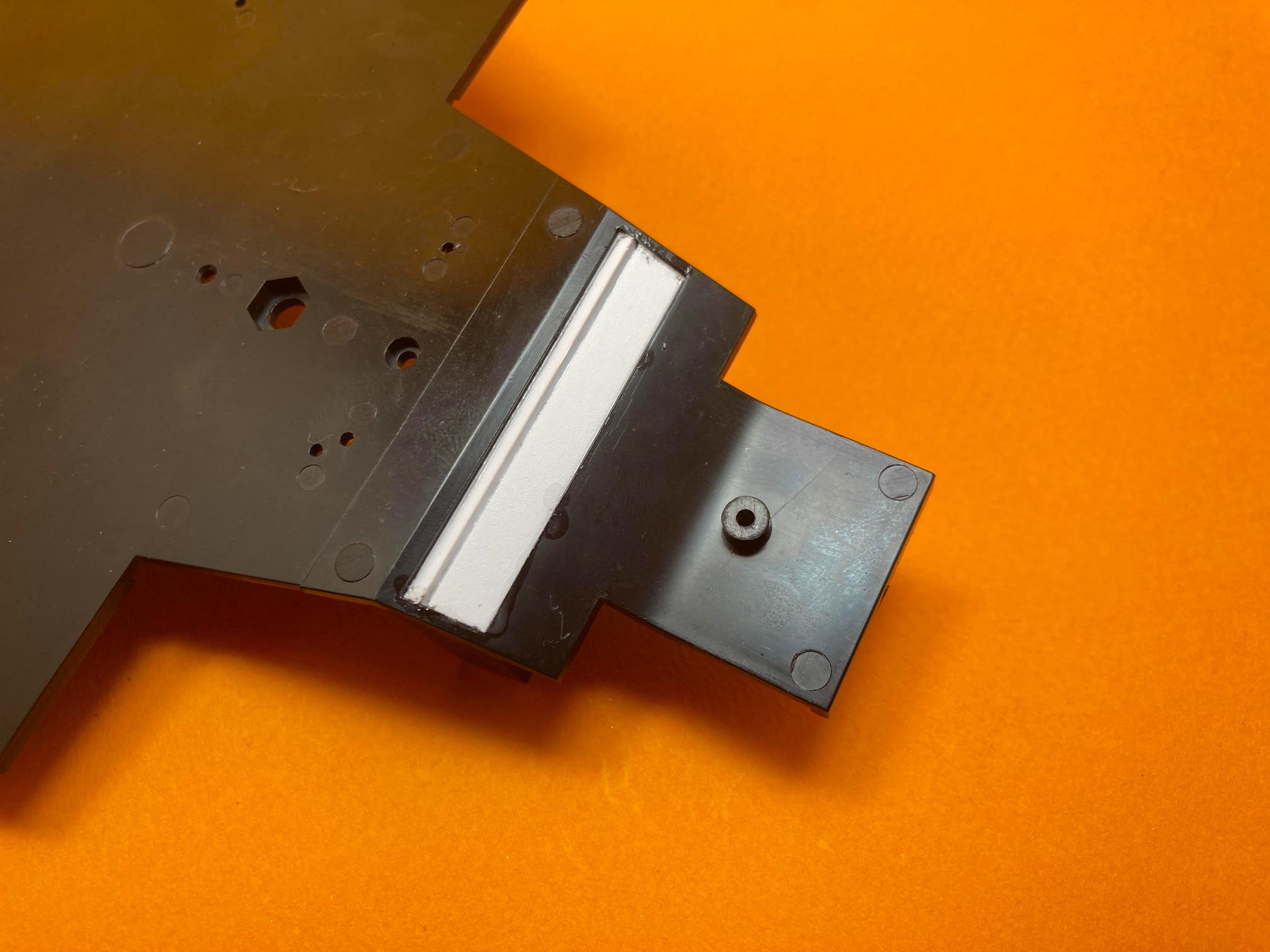
This images shows the fuel bladder access panel having been fitted in place. I began by placing one drop of glue at a point on the inside of access panel with the part placed exactly where I wanted it. The goal is to achieve a uniform recess/gap between the access panel and the tub. I put the drop of super glue on one of the arches and let it cure. I then adjusted how it fit the rest of the way around and then worked at gluing it in place all the way around on the inside. A shot of some "kicker" (super glue curing accelerator) secured it in place all the way around. Please note the orientation of the panel. The fuel fill needs to be on the upper right hand side of the opening.
Step 2

Moving to the front of the tub/monocoque, we need to remove the fairings that cover part of the front suspension.

You can now see the front suspensions fairings have been trimmed away.
I used an X-Acto hand saw with a short (in height) blade, so I had good control and didn't end up cutting into the tub.
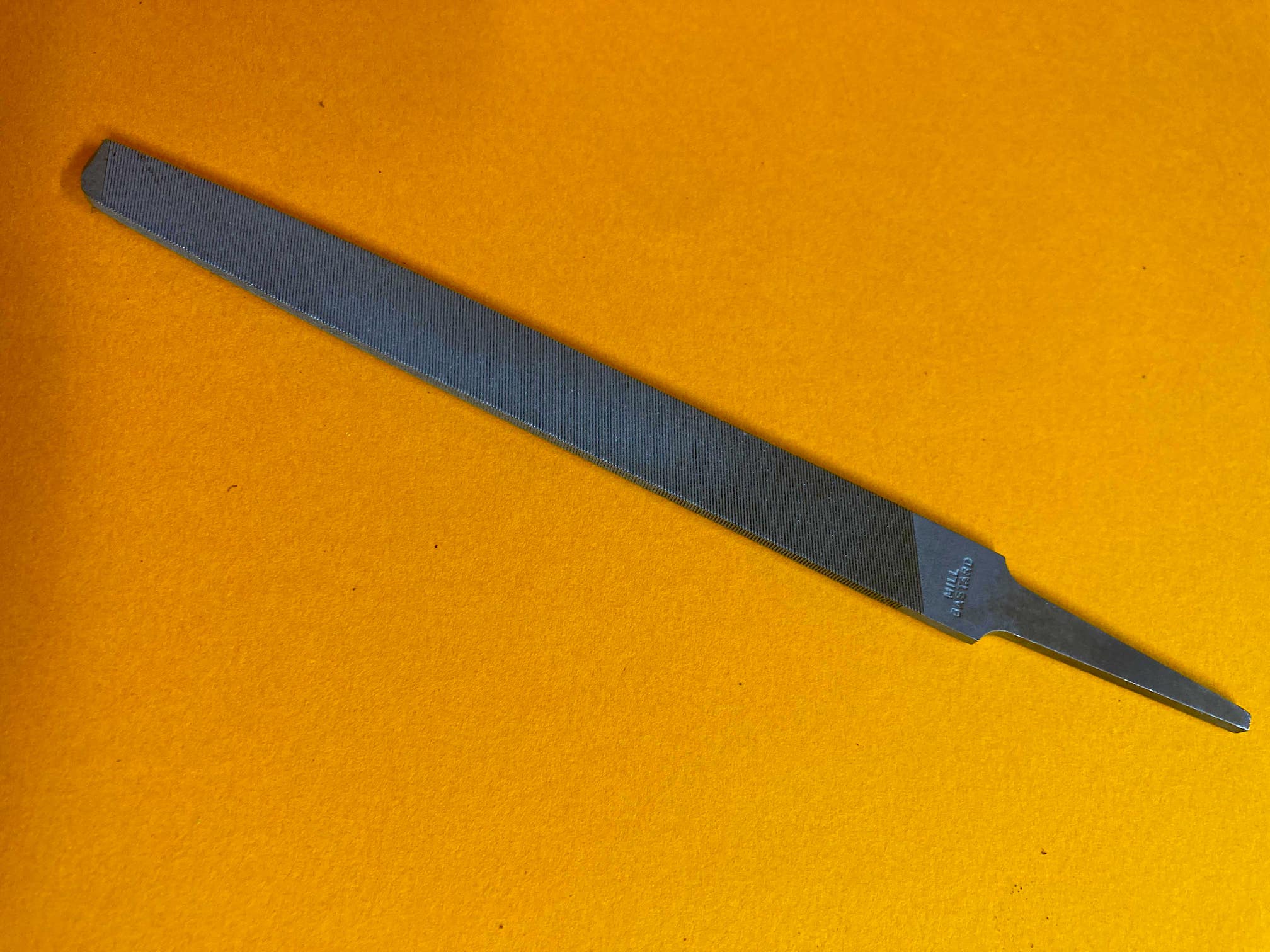
To finish off the area where the suspension fairings were cut, I used a flat, steel file to flatten the surface, but left a small footprint of where they were located. It's good to have a file card, a tool used to clean the flutes of the file, if it becomes clogged with either styrene or the filler used on other areas.

Both sides of the tub should look like this after the incorrect suspension fairings have been cut off and filed flat with a portion remaining to locate the new suspension fairings supplied in the Front Suspension Set.
View Steps 3-5
Step 3
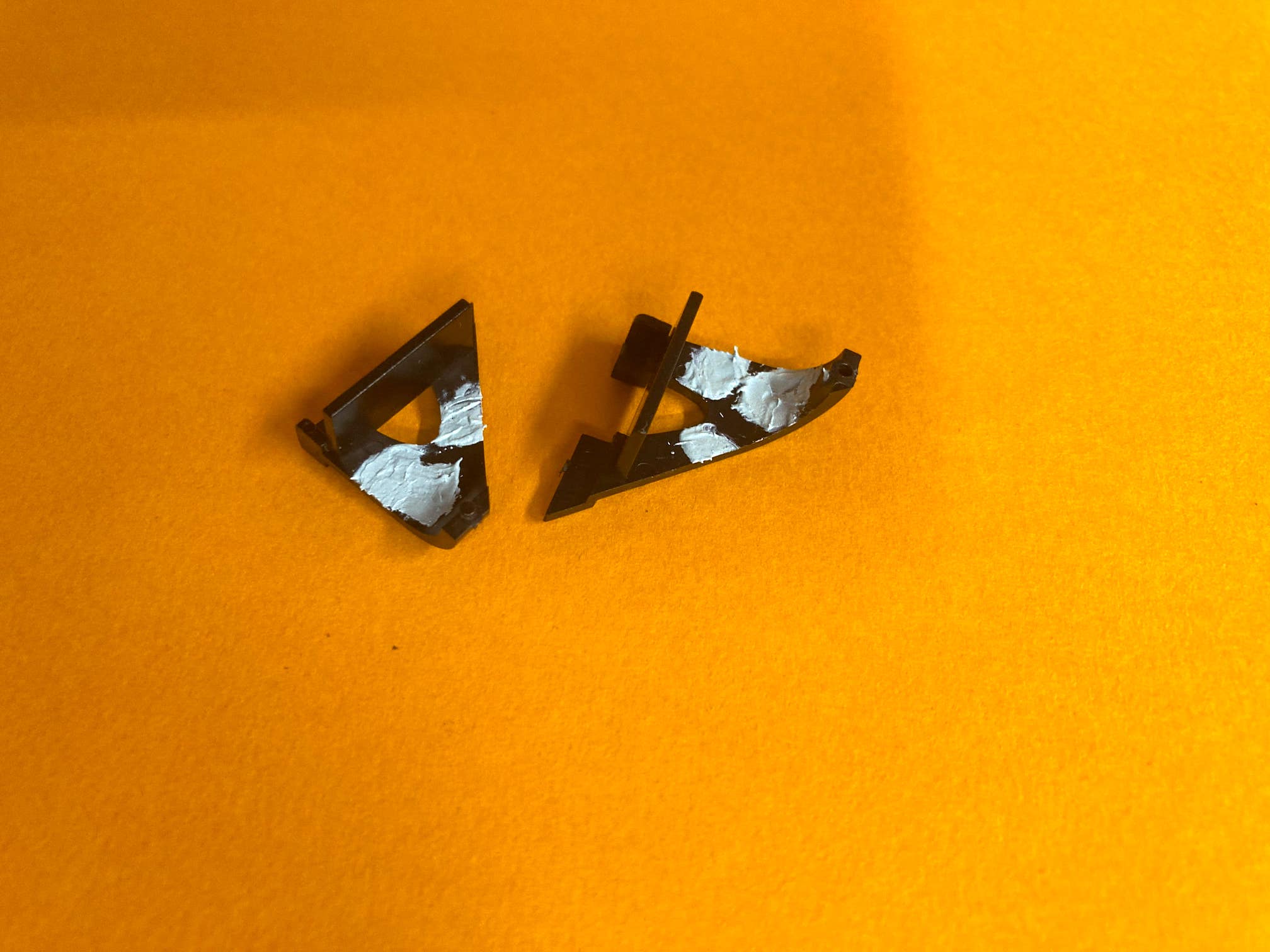
The image above shows the location where the rear of the front dampers attach. We will not be using the metal castings from the kit to attach them, and we will also be replacing the diamond shaped feature, replacing it with a 3D printed part. Again, I used an X-Acto saw to carefully cut away the diamond shape.

The openings need to be filled with pieces of styrene plastic. A company called Evergreen makes many shapes, sizes, and thicknesses of styrene to construct just about anything from scratch. I used some of their .040" rectangular shaped sticks, trimmed, fitted and glued into place to close them.


The first photo shows how this area has been filled with Evercoat polyester glazing putty to blend the surfaces together. The second photo shows the results after using a coarse sanding stick and then finishing the surface with a fine-tooth, flat, steel, file. Final sanding and prep will take place just before applying the high gloss black base. Once the gloss base coat has been applied and allowed ample time to dry, we can begin applying the carbon fiber decals. At that point, the tub will really begin to come to life and look as it should. It's all a lot of tedious work, but the effort will be worth it. The replacement diamond feature is included in the Front Suspension Set. The mounting brackets for the dampers will be provided in the Cockpit and Tub Set.
Step 4
The roll hoop in the kit isn’t accurate and it certainly is a couple of parts that require a lot of work. There are ejector pins on the inside of bother parts, sink marks on the outsides due to the plastic cooling, the seam which would need to be addressed inside and out, plus the two half-round bars that attach to the front aren’t event here.

The image shows a freshly printed roll hoop and the one painted black has the two half round sections added to the front face. These parts were used as a quick mock-up to make certain everything still fit when the body work is put on. There will also be special hardware provided that is accurate to the real car. We'll take another photo of the new roll bar along with the two other 3D printed parts applied to it, which will be a part of the Cockpit and Tub Set.
Step 5


The first image shows the kit part in its original form. The second photo shows the same part after a section has been cut away and the resulting opening has been filled with 040" / 1.016mm styrene has been bonded in place. A new cockpit bulkhead will be provided in the Cockpit & Tub Set, along with a new instrument panel. These parts needs to be modified so the fire suppression tank is in the correct position in relation to the bulkhead and the seat. When bonding styrene to other parts, I always use the solvents that actually dissolve the styrene, and once joined and solidified, they become one solid piece as though they were originally molded as one.
The underside will look similar after inserting the styrene piece.

I applied polyester glazing putty to the bottom side of the cockpit floor pan. I use it because it is a micro grain material that leaves an incredibly smooth, high-quality surface after being sanded. It can be primed, lightly sanded, and have a top coat applied with excellent results. The putty isn't cheap, but a can of it will last you nearly a lifetime, and it is simply the best. Evercoat is the only filler product I use.


To this point, I applied the polyester glazing putty and completed the initial round of sanding. Just prior to the last primer coat, I will take care of any final sanding work.


I applied an initial primer coat to help identify high and low spots during final sanding.
View Steps 6-#
Step 6

The electronics module is located inside the lefthand side pod. I decided to provide this as a 3D printed resin part because of where it it is located. To machine it from aluminum and have it anodized, or have it cast in metal just isn't worth the expense because it's somewhat hidden. I feel it is best to paint it gloss black and top coat it with an Alclad metallizer, along with adding some "weathering" detail, such as track dust and debris, to bring it to realize its true appearance.
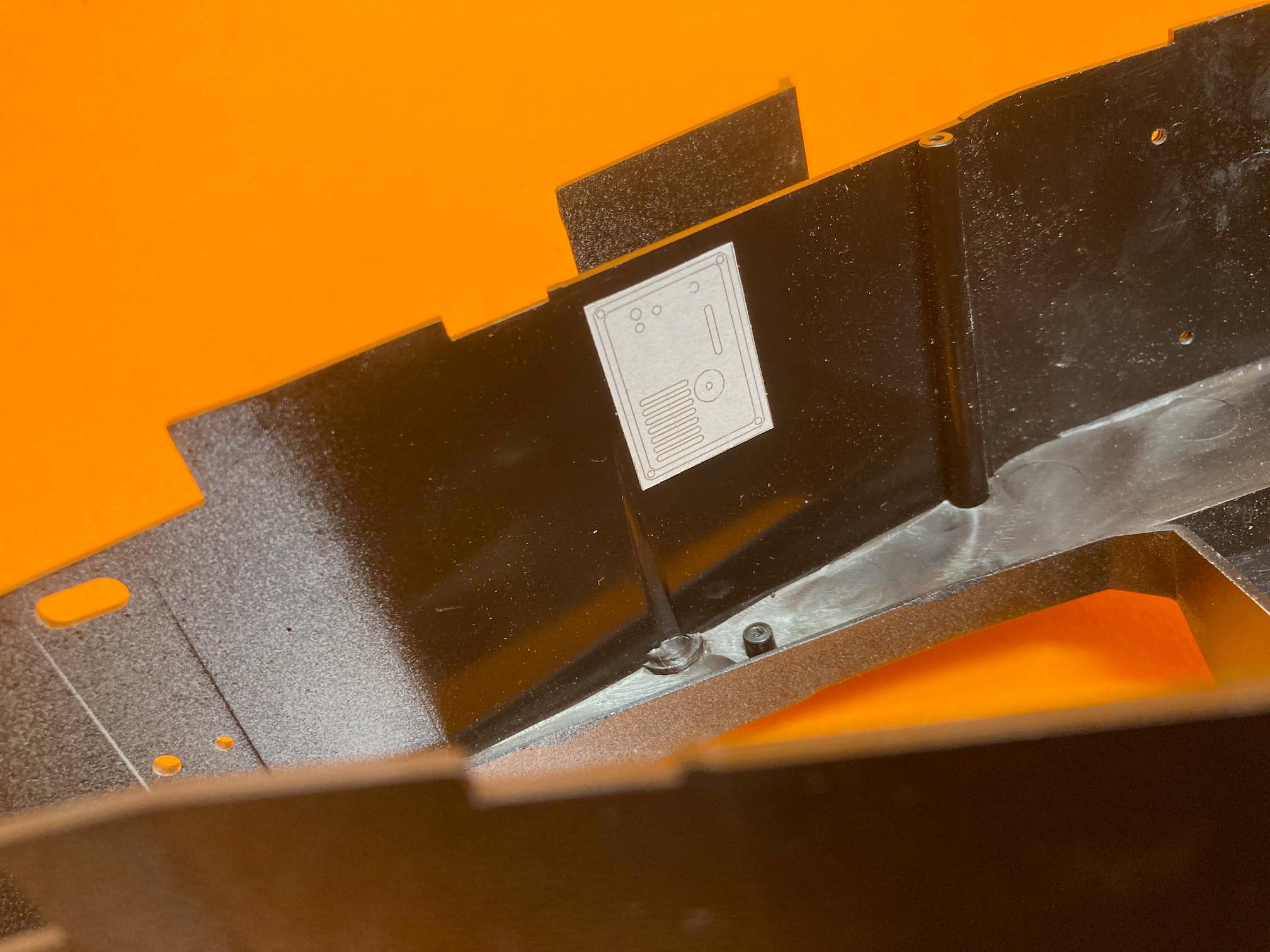
The template is to be placed to help with proper placement prior to cutting the opening for this electronics module.

The template now has primer lightly sprayed over it.

The template having been removed reveals the area to be cut out.

I drilled a bunch of holes around the perimeter of where the opening should be. This allowed me to use sprue cutters to remove the middle chunk of the material.

This is the opening completed, which much be perfectly square in order to accept the electronics module.

The electronics module is taped in place to check the fit and alignment. The module will be glued into place once painted and detailed.